Privacy statement: Your privacy is very important to Us. Our company promises not to disclose your personal information to any external company with out your explicit permission.
Variable frequency diode direct frequency modulation circuit
Now electronic enthusiasts network with you to learn the direct frequency modulation circuit of varactor diode:
(1) The principle of varicap diode frequency modulation There is the following relationship between the varactor diode junction capacitance Cj and the reverse bias voltage u applied across it:  Where C0 is the capacitance of the varactor diode at zero bias, uφ is the potential difference of the PN junction of the varactor diode, and is the change index of the junction capacitance.
2) Performance analysis of direct frequency modulation of varactor diodes The following is discussed in two cases.
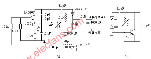
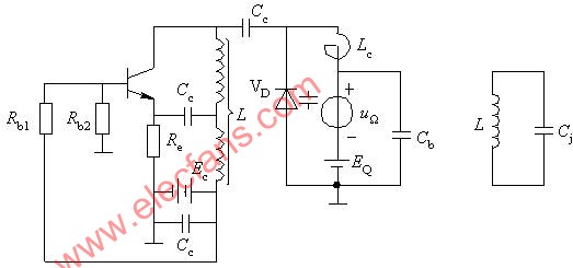
(1) Cj is the total capacitance of the loop. Figure 7-13 is a direct frequency modulation circuit of a varactor diode, Cj is connected to the loop as the total capacitance of the loop. Figure 7-13 (b) is a simplified high-frequency circuit of Figure 7-13 (a) oscillation circuit.
It can be seen that if uΩ (t) is added to the varactor tube, Cj will change with time (time-varying capacitance), as shown in Figure 7-14 (a).


Figure 7-14 Linear frequency modulation principle of varactor

Figure 7-19 Example of direct frequency modulation circuit of varactor diode?
(A) Actual circuit; (b) Equivalent circuit 
Contactar proveedor

Privacy statement: Your privacy is very important to Us. Our company promises not to disclose your personal information to any external company with out your explicit permission.

Fill in more information so that we can get in touch with you faster
Privacy statement: Your privacy is very important to Us. Our company promises not to disclose your personal information to any external company with out your explicit permission.